Saturday, October 30, 2021

A Project Named Clancy - IV. Marking and Cutting the Parts


In Build a Clancy the dimensions for each part
are given inline with the text, showing 
up in the book only when the part is used.

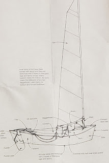
Build a Clancy proudly proclaims that a Clancy is made from only 28 basic parts.  These are primarily cut from marine grade plywood, with only parts like the keel, keelson, and rubrails made from solid timber.  All of the dimensions for each part can be found sprinkled throughout the book; dimensions for each part are given immediately before that part is installed).  This is where the plans from the New Yankee Workshop are helpful.  While the drawings and the way the dimensions are given are entirely identical to the book, they collect all the drawings into three handy pages, and include plywood layouts.  There is at least one error in the New Yankee plans -- 1/2" plywood is called out for the daggerboard trunk sides, but it really should be 1/4".

Anatomy of a Clancy

The plans call out for the near-mythical 4'x10' sheets of marine grade "Mahogany" or fir plywood.   On undertaking the project, I had resigned myself to the idea that I would have to scarph the requisite panels from 4'x8' okoume.  I was ready to submit an order to Edensaw, but, not wanting to wait the required few days for delivery, decided to call the more-local Midway Plywood to see if they have any in stock.  They were out of 4x8 okoume, but it turned out that they happened to have a supply of 4'x10' meranti.  It wasn't BS1088-level quality, but it was more than sufficient for my purposes.

Speaking of mythical plywood dimensions, a half-sheet of 1/2" plywood is specified for the transom and small amounts of  3/4" plywood is required for the daggerboard and mast step.  I had some pieces of both 1/2" and 3/4" plywood left over from previous projects that were large enough that I did not have to buy anything.  If that were not the situation, I would recommend avoiding buying 3/4" plywood and just buying a full sheet of 1/2" and using for the transom, laminating it up to 1 1/2" for the mast step, and laminating it with some offcut 1/4" to form the daggerboard.  Also, for reasons that are unclear, the plans specify an aluminum rudder, but I would use the 1/2" plywood for that too.

Plywood Layouts

Work begins by laying out the dimensions for each piece on the plywood.  Dimensions given in the plans are transferred to the plywood; I used a framing square, 12" combination square, 4' and 8' ft straight edges and a tape measure, but having a large T-square and 4-ft or longer metal ruler would make the effort immensely easier.  

Bulkhead dimensions


I measured each point and marked it with a punch.  The dimensions appear straightforward, though when you go to lay out the parts you find that they are unhelpfully, as in the case of the bulkheads, not all from the same datum -- sometimes you measure up from the bottom, sometimes down from the top, sometimes out from the center, sometimes in from the edge.   Translating this into something easy to use is good exercise in adding and subtracting fractions.  

After that, it was a game of connect the dots.  Straight edges could be connected the a ruler or straightedge...

...while stiff, long battens were used for the curves.  I used a 4' long, 1/4"x5/8" cedar strip for shorter curves like the tops of the bulkheads, and a 12' long, 3/4"x3/4" strip of mahogany for the hull sides.

Using a batten to connect the long sweeping curve
of the bottom.  You can see some unfairness midway 
up the curve.  Some adjustment was called for to
get this fair.

After marking all the parts, it is time to make some sawdust. The bottom panels, partial bulkheads and rudder cheeks cut, ensuring these parts are identical left and right and saving you from having to mark them all individually.  Long curves are cut with a circular saw...

...before switching to the jigsaw for tighter spaces.

The sheets with the deck and side panels can be stacked and cut at the same time too, as long as you remember that the bulkhead parts and deck trim are different between the two sheets.  I started by carefully cutting out the cockpit area from the decks so that I could mark the bulkheads on the offcut.   


The bulkheads can then be marked and cut.  On the aft bulkhead, I recommend (after learning the hard way) not full cutting out the access hole, instead leaving attached with a few 1-2" long tabs.  This leaves a nice surface to support the bulkhead on the jig.  Later, after the hull is assembled and off the jig, you can finish opening up the hull by cutting the tabs with a few swift swipes with a pull saw.

After bulkhead, semi cut.
Do not cut the hole in the
center all the way out.

Pretty soon, you have a large pile of Clancy parts.


While in the swing of cutting things out, I also milled all the solid timber.  The keel and keelson can be ripped to width on the table saw and the tapers at the ends cut with the circular saw.  

Keel

The table saw is also the tool of choice for milling the rubrails, stem, and cutwater.   The plans specify fir for some of the timber, but I used mahogany timber throughout.

When I built the Eastport Pram, I included a little bit of Solitude III in the new boat by cutting down some of the sapele from her original tabernacle into the pram's tiller.  I decided that the Clancy should also have a similar relic incorporated.  Having just replaced the boom gallows on Solitude, I decided to cut down the old one to form the Clancy's the knee and transom.  It is fun to know that these boats are all blood relatives.

Old boom gallows...

into a knee!


Saturday, October 23, 2021

A Project Named Clancy - III. Setting Up The Jig

The jig assembly (illustration from Build a Clancy)

Clancy is built on a jig -- a form that holds key structural elements in the correct position in three dimensional space so that they can be attached to each other.  The jig for Clancy is a 10-ft x 3-ft ladder frame made from 2x4s, with a vertical plywood "crutch" to hold the bulkhead and transom, a plywood center mold to give shape to the boat's midsection, and a piece of timber at the forward end of the jig for the top of the stem to land on. 

When building Clancy, it is useful to have both a copy of one of the Clancy books, and the drawings from the New Yankee Workshop.  The books contain step by step instructions and details not contained in the New Yankee plans/videos, but the New Yankee plans are superior than those in the book.  The New Yankee draftsmanship is better, plans for all parts are condensed to two sheets of paper, plywood layouts are included, etc. 

Test fit of the crutch and centre mold
Laying out jig parts


I started by marking and cutting out all of the plywood parts for the jig.  A 4'x8' sheet of 1/2" plywood (not marine grade!) is required for the jig.  I had a spare sheet of AC laying around that I used.   If not for having the plywood on hand, MDF would probably be a better choice, being easier to mark up precisely.  I used a combination of a measuring tape, carpenter's square and straightedge to lay out the parts.  Having a long T-square and metal straight edge rule would have made the job easier and more precise. 

Outer perimeter of the frame. Note the Eastport
Pram draped in plastic below.
 
The next step is to assemble the ladder frame.  The rails of the frame are 10-ft 2x4s, and the rungs a 3-ft lengths of 2x4, spaced per the dimensions in the plans.  Having very straight timber here is beneficial.  With the way the coronavirus pandemic has disrupted the lumber market, it was hard to find straight 10 footers at the local big box store!  All joints are reinforced by 12-in plywood gussets.  The plans call for gluing all joints, but between the gussets and attaching everything with screws, the frame is brutally strong, so I omitted the glue (which also makes it easier to disassemble later).  
Completed ladder frame


At this point, it is worth talking about the situation in the Lee Boatworks Shop.  It is full of boats.  In a space just the size of a very small 2 car garage (maybe a 1.5 car garage), there is a kayak on the wall (Redfish), a kayak on the ceiling (Pygmy), and a kayak in three parts on the floor (CLC Shearwater Sectional)  There's a rowboat against a wall (Fern), and a small sailing dinghy (CLC Eastport Pram) on the floor.  This is in addition to the shop tools, garden tools and storage typical to a garage.  There is no room to build a Clancy.  To solve this, I added legs and casters to the Clancy building jig, so that the Eastport Pram on the floor could be tucked under it.  So, I am literally building boats on top of boats.

Boats everywhere, and almost nowhere left to 
work! The plywood at the far end is for the jig 
and has already been cut down notably.

In the next installment I'll talk more about marking the plywood parts for Clancy, but it is worth noting that prior to finishing the jig, I found the ladder frame made a great table to hold the plywood sheets when I marked them and cut them out.  A scrap piece of plywood on top of the ladder also made a great surface for coating parts like the daggerboard case and rudder in epoxy.

The jig, now on legs, being used as a work table

With the frame complete (and freed from its duties as a table, the next step was to mark the centerline of the jig.  Marking the center of each end and snapping a chalk line would have worked, but I chose to give my laser level a workout.  

The crutch is cut out from 1/2" plywood, and has several slots cut into it which will be used to hold the center mold, and the bulkheads and transom in the correct position.  Some b2x2 blocking is added at each slot to give a surface to temporarily clamp/screw the bulkheads to.  The bulkheads and center mold slots are vertical, and the transom's is raked 22.5 deg.  Log #1, a 2x2 that is used to attach the crutch to the frame is lined up with one edge along the centerline and screwed to the frame.  The crutch is then attached to this.  This results in the left edge of the crutch being right on the centerline of the boat.  The crutch is held plumb with gussets.  When the bulkheads and transom are later put into position, their centerlines just need to be aligned with the left edge of the crutch, ensuring a straight boat. 

The jig from the behind...

...and ahead (log #3 has not been installed yet here)

The center mold slides onto the crutch and, after being made square with the crutch is screwed down to 2x2's, which are in turn secured to the ladder.  Logs #2 and #3, also 2x2's are aligned with their centers on the centerline of  jig.  Log #2 runs between the front of the jig and the first rung and is used to secure log #3 which is screwed to the top of it.  Log #3 is where the top of the stem will later be attached.

The jig itself was a simple and enjoyable carpentry project, but did take some time to get right.  I worked in a few hour-long sessions on weeknights, and, including the addition of the castered legs, probably spent 6 hours on it.  Everything needs to be aligned with the center of the jig, and squared up, but diligence here pays huge dividends later.  

Saturday, October 16, 2021

A Project Named Clancy - II. The Clancy Design

Clancy was billed by its chief promoter, Bob Pickett, as a "10-foot sailboat of exquisite form and commanding performance."  Weight is quoted at a car-toppable  85 lbs, and when coupled with it's 55 sq. ft sail, the boat is capable of planing "under the right conditions."

In Pickett's words, the boat was intended to be "the most sailboat you can squeeze out of a 10-sheet of plywood."  This is in refence to the fact that the boat was designed around the then-accessible (through Pickett's Flounder Bay Boat Lumber), but now nearly extinct 4x10 sheet of plywood. Three sheets of 1/4-in marine grade 10-footers comprise the hull bottom, sides, deck and bulkheads.  A (equally hard to find) half sheet of 1/2-in ply is also needed for the transom, kingplanks and daggerboard trunk, while 3/4-in ply is specified for the daggerboard.  Various pieces of solid timber are required for the keel, keelson and other miscellaneous structure.  Aluminum tubes are specified for the spars. 

Construction is cited as being stitch and glue, though this claim is not wholly accurate.  There is some similarities to a stitch and glue boat in the final product, in that it is a monocoque hull, made from plywood, held together with epoxy fillets and fiberglass.  There is, however, little in the method of construction that bares a resemblance to stitch and glue.  In stitch and glue, hull panels are cut to very precise shapes -- the shape of the panels wholly determining the hull's final form -- and then stitched together as the seams with wire before being permanently bonded with epoxy.  On Clancy, the hull is built upside-down on a jig.  The bulkheads, keelson, and stem are secured to the jig, and then the slightly oversized hull panels are attached and trimmed to size.  The method is a hybrid, with DNA from stitch and glue and plywood on frame, with just a little of Tolman skiff thrown in.  It is a method that is rewarding, fast, and easy for a first timer, though perhaps not any more so than stitch and glue.


In his introduction to his New Yankee Workshop episode on the Clancy,  Norm Abrams calls the Clancy of "refined model," yet a closer look at her lines do show some rough spots.   The boat is not unattractive over all, but plywood does not appear to have been the designer's most familiar medium.   The hull bottom is not developed, i.e. of a conical section so that the plywood can bend to it without being "tortured." The is evident from the fact that it is flat from the forward bulkhead to the midpoint of the cockpit, with some curvature or deadrise aft.  This, in turn causes the forward hull bottom to want to take an inverted "V" form, which has to be forced flat when the hull sides are installed.  There's an aggressive upsweep in the shear line that, if not unfair, seems.to be at least a little of of proportion.  Compared to its stitch and glue contemporaries from Pygmy or Devlin, Clancy is clearly a little less refined in design.  More unfairly, a look at modern boats such as Chesapeake Light Craft's Peapod shows just how far the art has come with the help of modern CAD/CAM tools and CNC machines.

Sunday, October 3, 2021

A Project Named Clancy - I. Introduction to Clancy


Introducing the latest boat building project at the Lee Boatworks: a Clancy.  

The story of the Clancy begins with Bob Pickett was something of a local fixture.  Born in 1929 and raised in Florida, Pickett was a boat nut.  He his wife Erica settled in Anacortes in 1971, opening Flounder Bay Boat Lumber.   His sister-in-law would later note that Pickett "had a strong sense of how to enjoy life, include others, and build community.  Boating did all three..."   He helped found OARS, a rowing club in Anacortes, and pushed for the establishment of Seafarer's Memorial Park.   He also took an interest in making boat building more accessible to amateur builders.  Along with journalist J.D. Brown, Pickett wrote "Rip, Strip and Row," his first do-it-yourself manual in 1985 for a cedar strip rowboat, the Cosine Wherry.  (side note: a few years ago, my Dad finished a Cosine Wherry originally begun be a cousin.) 

Bob Pickett

The boat was was to become Clancy was born as Pickett's second effort, developed "in response to the need for a safe, small, lightweight, high-performance sailboat of distinction that was fully within the reach of any beginning builder.  He commissioned the design from Richard S. Kolin, a Pacific Northwest boat designer, builder, and wooden boat teacher.  Known for more traditional small craft, such as the lapstrake as Heidi 12 skiff  and Catherine 14 Whitehall-style pulling boat, Kolin designed Clancy to be built as simply as possible using what Pickett described as stitch and glue, though in techinque it is more of a hybrid between stitch and glue and plywood-on-frame.  The 10-ft cat-rigged sailboat was named after Kolin's dog, a fact reflected in the Clancy's "C-Bone" class insignia.

Two books were spawned from the design effort, 1992's "Build a Clancy" and 1997's "A Boat Named Clancy" (I only have "Build a Clancy," so I do not know if or how different the books are).  As with "Rip, Strip, and Row," both Clancy books were authored by Pickett and Brown.  Supplies to build  Clancy were available through Flounder Bay, and Pickett arranged for sails and hardware packages to be readily available through local suppliers .Tech support was offered via the "Clancy Hotline" -- listed in 1992 at 1-206-293-2369 -- with Bob or Erica Pickett answering all your Clancy questions.

Norm Abrams' New Yankee Clancy
The boat was adopted by Seattle's Alternative School #1's to teach boat building in a classroom, and further rose to popularity when it was adopted as part of Seattle's Center for Wooden Boat's fleet, where Clancy's were built and used as instructional boats.  Flounder Bay also offered a Clancy Classroom.  The boat's true moment of fame, however, came in 1995, when Norm Abram built a Clancy during a special two-part episode of his PBS program, The New Yankee Workshop. 

The Picketts sold Flounder Bay Boat Lumber and retired around 2003.  Bob Pickett passed away in 2018.  A mural of Bob and Erica rowing a gig with members of OARS can be seen right across from the old Flounder Bay location on 3rd and O St, in Anacortes.

In "Build a Clancy," Pickett and Brown wrote that while Clancy is perfect for first time boat builders, "but veteran do-it-youselfers, experienced carpenters, and Old Salts, too, will enjoy the challenge."